- 您现在的位置:买卖IC网 > Sheet目录337 > LT3476EUHF#PBF (Linear Technology)IC LED DRVR HP CONST CURR 38-QFN
�� �
�
�LT3476�
�APPLICATIONS� INFORMATION�
�Ceramic� type� capacitors� using� X7R� dielectric� are� best� for�
�temperature� and� DC� bias� stability� of� the� capacitor� value.�
�All� ceramic� capacitors� exhibit� loss� of� capacitance� value�
�with� increasing� DC� voltage� bias,� so� it� may� be� necessary� to�
�choose� a� higher� value� capacitor� or� larger� case� size� to� get�
�the� required� capacitance� at� the� operating� voltage.� Always�
�check� that� the� voltage� rating� of� the� capacitor� is� sufficient.�
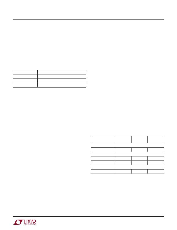
�Table� 3� shows� some� recommended� capacitor� vendors.�
�Table� 3.� Low-ESR� Surface� Mount� Capacitors�
�capacitor� that� is� 1:1000� the� value� of� the� compensation�
�capacitor.� In� the� buck� configuration,� an� additional� tech-�
�nique� is� available.� The� filter� capacitor� between� the� CAP�
�node� and� the� LED� bottom� (see� the� Typical� Application� on�
�the� first� page)� can� be� moved� to� between� the� LED� top� and�
�the� LED� bottom.� This� circuit� change� places� the� inductor�
�ripple� current� through� the� sense� resistor,� which� improves�
�pulse-skipping� behavior.� There� is� usually� less� than� 1%�
�impact� to� the� current� regulation� point.�
�VENDOR�
�TYPE�
�SERIES�
�Diode� Selection�
�Taiyo-Yuden� Ceramic� X5R,� X7R�
�AVX� Ceramic� X5R,� X7R�
�Murata� Ceramic� X5R,� X7R�
�Compensation� Design�
�The� LT3476� uses� an� internal� transconductance� error�
�amplifier� whose� V� C� output� compensates� the� control� loop.�
�The� external� inductor,� output� capacitor,� and� compensa-�
�tion� resistor� and� capacitor� determine� the� loop� stability.�
�The� inductor� and� output� capacitor� are� chosen� based� on�
�performance,� size� and� cost.� The� compensation� resistor�
�and� capacitor� at� V� C� are� selected� to� optimize� control� loop�
�stability.� The� component� values� shown� in� the� typical� ap-�
�plications� circuits� yield� stable� operation� over� the� given�
�range� of� input-to-output� voltages� and� load� currents.� For�
�most� buck� applications,� a� small� filter� capacitor� (1μF� or�
�less)� across� the� load� is� desirable.� In� this� case,� a� 10nF�
�compensation� capacitor� at� V� C� is� usually� quite� adequate.�
�A� compensation� resistor� of� 5k� placed� between� the� V� C�
�output� and� the� compensation� capacitor� minimizes� channel-�
�to-channel� interaction� by� reducing� transient� recovery� time.�
�The� boost� configuration� will� have� a� larger� output� capacitor,�
�2.2μF� to� 10μF.�
�The� following� circuit� techniques� involving� the� compensa-�
�tion� pin� may� be� helpful� where� there� is� a� large� variation� in�
�programmed� LED� current,� or� a� large� input� supply� range� is�
�expected.� At� low� duty� cycles� (T� ON� less� than� 350ns)� and� low�
�average� inductor� current� (less� than� 500mA),� the� LT3476�
�may� start� to� skip� switching� pulses� to� maintain� output�
�regulation.� Pulse-skipping� mode� is� usually� less� desirable�
�because� it� leads� to� increased� ripple� current� in� the� LED.�
�To� improve� the� onset� of� pulse-skipping� behavior,� place� a�
�capacitor� between� the� SW� node� and� the� compensation�
�The� Schottky� rectifier� conducts� current� during� the� interval�
�when� the� switch� is� turned� off.� Select� a� diode� with� V� R� rated�
�for� the� maximum� SW� voltage.� For� boost� circuits� that� may�
�use� the� output� disconnect� feature,� the� diode� should� be�
�rated� for� at� least� 40V.� It� is� not� necessary� that� the� forward�
�current� rating� of� the� diode� equal� the� switch� current� limit.�
�The� average� current� I� F� through� the� diode� is� a� function�
�of� the� switch� duty� cycle,� so� select� a� diode� with� forward�
�current� rating� of� I� F� =� 1.5A� ?� (1-D).� If� using� the� PWM� fea� -�
�ture� for� dimming,� it� may� also� be� important� to� consider�
�diode� leakage� from� the� output� (especially� at� hot)� during�
�the� PWM� low� interval.� Table� 4� has� some� recommended�
�component� vendors.�
�Table� 4.� Schottky� Diodes�
�V� R� I� AVE� V� F� AT� 1A�
�PART� NUMBER� (V)� (A)� (mV)�
�On� Semiconductor�
�MBRM140� 40� 1� 550�
�Diodes� Inc.�
�DFLS140L� 40� 1� 550�
�B140� HB� 40� 1� 530�
�NXP� Semiconductor�
�PMEG4010EJ� 40� 1� 540�
�Programming� the� LED� Current�
�The� LED� Current� is� programmed� using� an� external� sense�
�resistor� in� series� with� the� load.� This� method� allows� flex-�
�ibility� in� driving� the� load� (i.e.,� sensing� one� of� several� parallel�
�strings)� while� maintaining� good� accuracy.� The� V� ADJ� input�
�sets� the� voltage� regulation� threshold� across� the� external�
�sense� resistor� between� 10mV� and� 120mV.� A� 1.05V� refer-�
�ence� output� (REF)� is� provided� to� drive� the� V� ADJ� pins� either�
�3476fb�
�9�
�发布紧急采购,3分钟左右您将得到回复。
相关PDF资料
LT3477EFE#PBF
IC LED DRVR HP CONS CURR 20TSSOP
LT3478IFE#PBF
IC LED DRVR HP CONS CURR 16TSSOP
LT3486EFE#PBF
IC LED DRVR WHITE BCKLGT 16TSSOP
LT3491EDC#TRMPBF
IC LED DRIVER WHITE BCKLGT 6-DFN
LT3492IFE#TRPBF
IC LED DVR HP CONST CURR 28TSSOP
LT3496IUFD#PBF
IC LED DRVR WHT/RGB BCKLT 28-QFN
LT3497EDDB#TRMPBF
IC LED DRIVR WHITE BCKLGT 10-DFN
LT3498EDDB#TRPBF
IC LED DRVR WT/OLED BCKLGT 12DFN
相关代理商/技术参数
LT3476EUHF#TR
制造商:Linear Technology 功能描述:SP-SWREG/LED Driver, High Current Quad Output LED Driver in QFN (5x7)
LT3476EUHF#TRPBF
功能描述:IC LED DRVR HP CONST CURR 38-QFN RoHS:是 类别:集成电路 (IC) >> PMIC - LED 驱动器 系列:- 标准包装:6,000 系列:- 恒定电流:- 恒定电压:- 拓扑:开路漏极,PWM 输出数:4 内部驱动器:是 类型 - 主要:LED 闪烁器 类型 - 次要:- 频率:400kHz 电源电压:2.3 V ~ 5.5 V 输出电压:- 安装类型:表面贴装 封装/外壳:8-VFDFN 裸露焊盘 供应商设备封装:8-HVSON 包装:带卷 (TR) 工作温度:-40°C ~ 85°C 其它名称:935286881118PCA9553TK/02-TPCA9553TK/02-T-ND
LT3476EUHF-PBF
制造商:LINER 制造商全称:Linear Technology 功能描述:High Current Quad Output LED Driver
LT3476EUHF-TR
制造商:LINER 制造商全称:Linear Technology 功能描述:High Current Quad Output LED Driver
LT3476EUHF-TRPBF
制造商:LINER 制造商全称:Linear Technology 功能描述:High Current Quad Output LED Driver
LT3476IUHF#PBF
功能描述:IC LED DRVR HP CONST CURR 38QFN RoHS:是 类别:集成电路 (IC) >> PMIC - LED 驱动器 系列:- 标准包装:6,000 系列:- 恒定电流:- 恒定电压:- 拓扑:开路漏极,PWM 输出数:4 内部驱动器:是 类型 - 主要:LED 闪烁器 类型 - 次要:- 频率:400kHz 电源电压:2.3 V ~ 5.5 V 输出电压:- 安装类型:表面贴装 封装/外壳:8-VFDFN 裸露焊盘 供应商设备封装:8-HVSON 包装:带卷 (TR) 工作温度:-40°C ~ 85°C 其它名称:935286881118PCA9553TK/02-TPCA9553TK/02-T-ND
LT3476IUHF#TRPBF
功能描述:IC LED DRVR HP CONST CURR 38QFN RoHS:是 类别:集成电路 (IC) >> PMIC - LED 驱动器 系列:- 标准包装:6,000 系列:- 恒定电流:- 恒定电压:- 拓扑:开路漏极,PWM 输出数:4 内部驱动器:是 类型 - 主要:LED 闪烁器 类型 - 次要:- 频率:400kHz 电源电压:2.3 V ~ 5.5 V 输出电压:- 安装类型:表面贴装 封装/外壳:8-VFDFN 裸露焊盘 供应商设备封装:8-HVSON 包装:带卷 (TR) 工作温度:-40°C ~ 85°C 其它名称:935286881118PCA9553TK/02-TPCA9553TK/02-T-ND
LT3477
制造商:LINER 制造商全称:Linear Technology 功能描述:Full-Featured LED Driver with 1.5A Switch Current